Solution Description
Head Sheave/ Sheave Pulley/Lifting Products Xihu (West Lake) Dis. Wheel Device
Introduction:
Mine hoist can be divided into 2 kinds 1 kind is JKE sequence one rope mining hoist and the other is Multi-rope friction hoist.
This sequence mine hoist which includes 2m-5m single tubular and double tubular varieties, and can be utilised for mining hoist, staff lifting and materials and tools descending from vertical shafts or inclined shafts of coal, metallic and nonmetal ores.
JK mine hoist is mainly used in inclined roadways and wells of coal mines, metal mines and non-metal mines to hoist or lower personnel and materials.
Specialized parameters:
| Model | Drum | Tension PF |
Tension Differe |
Rope Diameter |
Lift peak (m) | Max Speed |
Reduce pace ratio |
Motor Pace |
||||||
| Number | Dia | Width | 1-layer | two-layer | 3-layer |
|||||||||
| m | KN | mm | m | m/s | r/min | |||||||||
| JK-2×1.5/twenty | 1 | 2. | 1.five | 62 | 24 | 305 | 650 | 1571 | 5.2 | 20. | 1000 | |||
| JK-2×1.5/31.five | 31.five | |||||||||||||
| JK-2×1.8/twenty | 1.80 | 375 | 797 | 1246 | twenty. | |||||||||
| JK-2×1.8/31.5 | 31.five | |||||||||||||
| JK-2.5×2/20 | 2.five | 2.00 | 83 | 28 | 448 | 945 | 1475 | 5. | 20. | 750 | ||||
| JK-2.5×2/31.five | 31.five | |||||||||||||
| JK-2.5×2.3/20 | 2.30 | 525 | 1100 | 1712 | 20. | |||||||||
| JK-2.5×2.3/31.5 | 31.five | |||||||||||||
| JK-3×2.2/twenty | 3. | 2.20 | 135 | 36 | 458 | 966 | 1513 | six. | twenty. | |||||
| 2JK-2×1/11.2 | two | 2. | 1.00 | 62 | 40 | 24 | 182 | 406 | 652 | 7. | 11.two | |||
| 2JK-2×1/twenty | twenty. | |||||||||||||
| 2JK-2×1/31.five | 31.five | |||||||||||||
| 2JK-2×1.twenty five/eleven.2 | 1.twenty five | 242 | 528 | 838 | 11.two | |||||||||
| 2JK-2×1.25/twenty | twenty. | |||||||||||||
| 2JK-2×1.25/31.five | 31.5 | |||||||||||||
| 2JK-2.5×1.2/eleven.two | 2.five | 1.twenty | 83 | 65 | 28 | 843 | 8.8 | 11.two | ||||||
| 2JK-2.5×1.2/twenty | twenty. | |||||||||||||
| 2JK-2.5×1.2/31.five | 31.five | |||||||||||||
| 2JK-2.5×1.5/11.two | 2.five | 1.fifty | 83 | 65 | 28 | 319 | 685 | 1080 | 8.8 | eleven.2 | ||||
| 2JK-2.5×1.5/twenty | 20. | |||||||||||||
| 2JK-2.5×1.5/31.five | 31.five | |||||||||||||
| 2JK-3×1.5/eleven.2 | 3. | 135 | 90 | 36 | 289 | 624 | 994 | 10.5 | 11.two | |||||
| 2JK-3×1.5/twenty | 20. | |||||||||||||
| 2JK-3×1.5/31.5 | 31.5 | |||||||||||||
| 2JK-3×1.8/eleven.two | 1.eighty | 362 | 770 | 1217 | 11.two | |||||||||
| 2JK-3×1.8/twenty | 20. | |||||||||||||
| 2JK-3×1.8/31.5 | 31.five | |||||||||||||
| 2JK-3.5×1.7/eleven.2 | 3.five | 1.70 | 170 | 115 | 40 | 349 | 746 | – | 12.six | 11.two | ||||
| 2JK-3.5×1.7/twenty | 20. | |||||||||||||
| 2JK-3.5×2.1/eleven.2 | 2.10 | 450 | 950 | – | 11.2 | |||||||||
| 2JK-3.5×2.1/eleven.two | 20. | |||||||||||||
| 2JK-4×2.1/10 | 4. | 245 | 160 | 48 | 421 | 891 | – | 12.6 | 10. | 600 | ||||
| 2JK-4×2.1/11.two | 11.2 | |||||||||||||
| 2JK-4×2.1/twenty | 20. | |||||||||||||
| 2JK-5×2.3/ten | 5. | 2.thirty | 280 | 180 | 52 | 533 | – | – | 12 | 10. | 500 | |||
| 2JK-5×2.3/11.two | ||||||||||||||
Possible defects:
| Defect | Leads to |
| Unfilled sections | Insufficient material Low pouring temperature |
| Porosity | Melt temperature is too high Non-uniform cooling rate Sand has low permeability |
| Hot tearing | Non-uniform cooling rate |
| Surface projections | Erosion of sand mold interior A crack in the sand mold Mold halves shift |
FAQ
Q: How about the high quality of your items?
A: Our devices are made strictly in accordance to national and international requirements, and we get a examination on each and every tools ahead of supply.
Q: How about the value?
A: We are manufactory, and we can give you decrease price than those trade businesses. Besides, consumers from Made in China can get a low cost.
Q: Do you give following-sale services?
A: Of course. The warranty interval of our equipment is 1 year, and we have a skilled following-sale crew to immediately and extensively fix your problems.
Q: Do you give gear procedure instruction?
A: Indeed. We can send expert engineers to the functioning web site for tools installation, adjustment, and procedure coaching. All of our engineers have passports.
|
US $10,000-150,000 / Ton | |
1 Ton (Min. Order) |
###
| Certification: | CE, ISO 9001:2008 |
|---|---|
| Standard: | ASME, BS, ANSI, GB, ASTM, DIN |
| Surface Treatment: | Sand Blast |
| Manufacturing Process: | Casting |
| Material: | Alloy Steel |
| Name: | Shaft Lifting |
###
| Customization: |
Available
|
|---|
###
| Model | Drum | Tension PF |
Tension Differe |
Rope Diameter |
Lift height (m) | Max Speed |
Reduce speed ratio |
Motor Speed |
||||||
| Number | Dia | Width | 1-layer | 2-layer | 3-layer |
|||||||||
| m | KN | mm | m | m/s | r/min | |||||||||
| JK-2×1.5/20 | 1 | 2.0 | 1.5 | 62 | 24 | 305 | 650 | 1025 | 5.2 | 20.0 | 1000 | |||
| JK-2×1.5/31.5 | 31.5 | |||||||||||||
| JK-2×1.8/20 | 1.80 | 375 | 797 | 1246 | 20.0 | |||||||||
| JK-2×1.8/31.5 | 31.5 | |||||||||||||
| JK-2.5×2/20 | 2.5 | 2.00 | 83 | 28 | 448 | 945 | 1475 | 5.0 | 20.0 | 750 | ||||
| JK-2.5×2/31.5 | 31.5 | |||||||||||||
| JK-2.5×2.3/20 | 2.30 | 525 | 1100 | 1712 | 20.0 | |||||||||
| JK-2.5×2.3/31.5 | 31.5 | |||||||||||||
| JK-3×2.2/20 | 3.0 | 2.20 | 135 | 36 | 458 | 966 | 1513 | 6.0 | 20.0 | |||||
| 2JK-2×1/11.2 | 2 | 2.0 | 1.00 | 62 | 40 | 24 | 182 | 406 | 652 | 7.0 | 11.2 | |||
| 2JK-2×1/20 | 20.0 | |||||||||||||
| 2JK-2×1/31.5 | 31.5 | |||||||||||||
| 2JK-2×1.25/11.2 | 1.25 | 242 | 528 | 838 | 11.2 | |||||||||
| 2JK-2×1.25/20 | 20.0 | |||||||||||||
| 2JK-2×1.25/31.5 | 31.5 | |||||||||||||
| 2JK-2.5×1.2/11.2 | 2.5 | 1.20 | 83 | 65 | 28 | 843 | 8.8 | 11.2 | ||||||
| 2JK-2.5×1.2/20 | 20.0 | |||||||||||||
| 2JK-2.5×1.2/31.5 | 31.5 | |||||||||||||
| 2JK-2.5×1.5/11.2 | 2.5 | 1.50 | 83 | 65 | 28 | 319 | 685 | 1080 | 8.8 | 11.2 | ||||
| 2JK-2.5×1.5/20 | 20.0 | |||||||||||||
| 2JK-2.5×1.5/31.5 | 31.5 | |||||||||||||
| 2JK-3×1.5/11.2 | 3.0 | 135 | 90 | 36 | 289 | 624 | 994 | 10.5 | 11.2 | |||||
| 2JK-3×1.5/20 | 20.0 | |||||||||||||
| 2JK-3×1.5/31.5 | 31.5 | |||||||||||||
| 2JK-3×1.8/11.2 | 1.80 | 362 | 770 | 1217 | 11.2 | |||||||||
| 2JK-3×1.8/20 | 20.0 | |||||||||||||
| 2JK-3×1.8/31.5 | 31.5 | |||||||||||||
| 2JK-3.5×1.7/11.2 | 3.5 | 1.70 | 170 | 115 | 40 | 349 | 746 | – | 12.6 | 11.2 | ||||
| 2JK-3.5×1.7/20 | 20.0 | |||||||||||||
| 2JK-3.5×2.1/11.2 | 2.10 | 450 | 950 | – | 11.2 | |||||||||
| 2JK-3.5×2.1/11.2 | 20.0 | |||||||||||||
| 2JK-4×2.1/10 | 4.0 | 245 | 160 | 48 | 421 | 891 | – | 12.6 | 10.0 | 600 | ||||
| 2JK-4×2.1/11.2 | 11.2 | |||||||||||||
| 2JK-4×2.1/20 | 20.0 | |||||||||||||
| 2JK-5×2.3/10 | 5.0 | 2.30 | 280 | 180 | 52 | 533 | – | – | 12 | 10.0 | 500 | |||
| 2JK-5×2.3/11.2 | ||||||||||||||
###
| Defect | Causes |
| Unfilled sections | Insufficient material Low pouring temperature |
| Porosity | Melt temperature is too high Non-uniform cooling rate Sand has low permeability |
| Hot tearing | Non-uniform cooling rate |
| Surface projections | Erosion of sand mold interior A crack in the sand mold Mold halves shift |
|
US $10,000-150,000 / Ton | |
1 Ton (Min. Order) |
###
| Certification: | CE, ISO 9001:2008 |
|---|---|
| Standard: | ASME, BS, ANSI, GB, ASTM, DIN |
| Surface Treatment: | Sand Blast |
| Manufacturing Process: | Casting |
| Material: | Alloy Steel |
| Name: | Shaft Lifting |
###
| Customization: |
Available
|
|---|
###
| Model | Drum | Tension PF |
Tension Differe |
Rope Diameter |
Lift height (m) | Max Speed |
Reduce speed ratio |
Motor Speed |
||||||
| Number | Dia | Width | 1-layer | 2-layer | 3-layer |
|||||||||
| m | KN | mm | m | m/s | r/min | |||||||||
| JK-2×1.5/20 | 1 | 2.0 | 1.5 | 62 | 24 | 305 | 650 | 1025 | 5.2 | 20.0 | 1000 | |||
| JK-2×1.5/31.5 | 31.5 | |||||||||||||
| JK-2×1.8/20 | 1.80 | 375 | 797 | 1246 | 20.0 | |||||||||
| JK-2×1.8/31.5 | 31.5 | |||||||||||||
| JK-2.5×2/20 | 2.5 | 2.00 | 83 | 28 | 448 | 945 | 1475 | 5.0 | 20.0 | 750 | ||||
| JK-2.5×2/31.5 | 31.5 | |||||||||||||
| JK-2.5×2.3/20 | 2.30 | 525 | 1100 | 1712 | 20.0 | |||||||||
| JK-2.5×2.3/31.5 | 31.5 | |||||||||||||
| JK-3×2.2/20 | 3.0 | 2.20 | 135 | 36 | 458 | 966 | 1513 | 6.0 | 20.0 | |||||
| 2JK-2×1/11.2 | 2 | 2.0 | 1.00 | 62 | 40 | 24 | 182 | 406 | 652 | 7.0 | 11.2 | |||
| 2JK-2×1/20 | 20.0 | |||||||||||||
| 2JK-2×1/31.5 | 31.5 | |||||||||||||
| 2JK-2×1.25/11.2 | 1.25 | 242 | 528 | 838 | 11.2 | |||||||||
| 2JK-2×1.25/20 | 20.0 | |||||||||||||
| 2JK-2×1.25/31.5 | 31.5 | |||||||||||||
| 2JK-2.5×1.2/11.2 | 2.5 | 1.20 | 83 | 65 | 28 | 843 | 8.8 | 11.2 | ||||||
| 2JK-2.5×1.2/20 | 20.0 | |||||||||||||
| 2JK-2.5×1.2/31.5 | 31.5 | |||||||||||||
| 2JK-2.5×1.5/11.2 | 2.5 | 1.50 | 83 | 65 | 28 | 319 | 685 | 1080 | 8.8 | 11.2 | ||||
| 2JK-2.5×1.5/20 | 20.0 | |||||||||||||
| 2JK-2.5×1.5/31.5 | 31.5 | |||||||||||||
| 2JK-3×1.5/11.2 | 3.0 | 135 | 90 | 36 | 289 | 624 | 994 | 10.5 | 11.2 | |||||
| 2JK-3×1.5/20 | 20.0 | |||||||||||||
| 2JK-3×1.5/31.5 | 31.5 | |||||||||||||
| 2JK-3×1.8/11.2 | 1.80 | 362 | 770 | 1217 | 11.2 | |||||||||
| 2JK-3×1.8/20 | 20.0 | |||||||||||||
| 2JK-3×1.8/31.5 | 31.5 | |||||||||||||
| 2JK-3.5×1.7/11.2 | 3.5 | 1.70 | 170 | 115 | 40 | 349 | 746 | – | 12.6 | 11.2 | ||||
| 2JK-3.5×1.7/20 | 20.0 | |||||||||||||
| 2JK-3.5×2.1/11.2 | 2.10 | 450 | 950 | – | 11.2 | |||||||||
| 2JK-3.5×2.1/11.2 | 20.0 | |||||||||||||
| 2JK-4×2.1/10 | 4.0 | 245 | 160 | 48 | 421 | 891 | – | 12.6 | 10.0 | 600 | ||||
| 2JK-4×2.1/11.2 | 11.2 | |||||||||||||
| 2JK-4×2.1/20 | 20.0 | |||||||||||||
| 2JK-5×2.3/10 | 5.0 | 2.30 | 280 | 180 | 52 | 533 | – | – | 12 | 10.0 | 500 | |||
| 2JK-5×2.3/11.2 | ||||||||||||||
###
| Defect | Causes |
| Unfilled sections | Insufficient material Low pouring temperature |
| Porosity | Melt temperature is too high Non-uniform cooling rate Sand has low permeability |
| Hot tearing | Non-uniform cooling rate |
| Surface projections | Erosion of sand mold interior A crack in the sand mold Mold halves shift |
What Is a Pulley?
The pulley is a wheel mounted on a shaft or axle. Its purpose is to support the movement of a cable that is taut. This cable transfers power to a shaft. However, there are certain safety precautions that you should follow when using a pulley. Read on to learn more! Listed below are common uses and their main parts. Listed below are some of the benefits of using a pulley.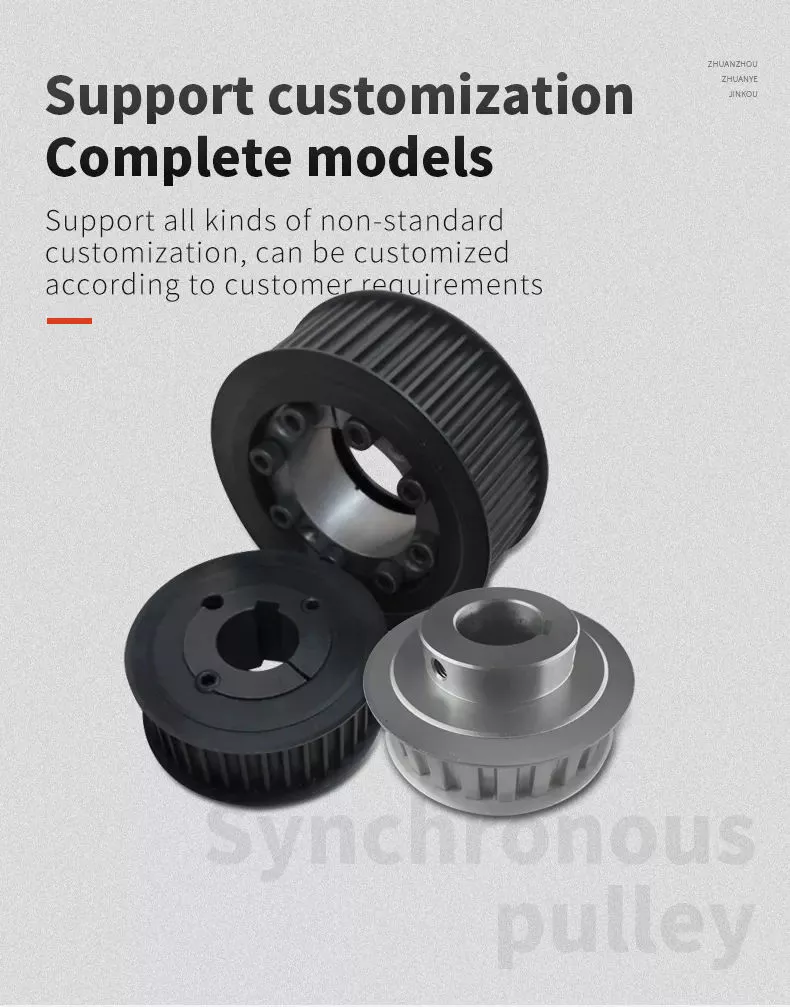
Common uses of a pulley
A pulley is a common mechanical device used to increase the force needed to lift a heavy object. Most commonly, these devices are used in construction equipment. These machines use high-tension ropes to transfer heavy objects from one floor to another. Other common uses of a pulley include buckets and flagpoles. These devices are extremely useful in a wide range of applications. To learn more about the common uses of pulleys, keep reading.
A pulley is a wheel with grooves for holding rope. Its purpose is to change the direction and point at which a pulling force acts. It is usually used in sets to reduce the amount of force needed to lift a load, but the work involved is similar. Pulleys are also used in rock climbing devices. For many applications, a pulley is a vital part of construction.
The most common use of a pulley involves hoisting and lowering a flag. Other examples include clotheslines, bird feeders, and escalators. Pulleys are also commonly used on oil derricks. Many other common applications include hoisting and lowering garage doors. Pulley systems are also used in engines and cranes. For more information, check out our interactive pulley diagram!
Pulleys can also be used to lower total work required for a task. In many cases, a pulley will consist of two parts: the pulley hub and the shaft pulley. The hub clamps the shaft pulley, while the pulley itself is connected to the motor or other device. If you’re looking for a pulley, it’s important to learn how it works.
The most common uses for a pulley involve lifting heavy objects, and the mechanism used to lift them is known as a pulley. A pulley is an industrial device that uses two wheels to reduce the force needed to lift a weight. The pulley reduces this force by half by allowing the user to pull on the rope four times as far. The pulley also allows for a smaller lifting distance.
Main parts of a pulley
A pulley consists of the main element of a system. This is typically a cable, rope, belt, or chain. There are two basic types of pulleys – a Driver Pulley and a Follower Pulley. Pulleys are available in small and large sizes. The periphery part of the pulley is called the Face, and the protruding middle part is called the Crown. A pulley’s face can be round, rectangular, or even “V” shaped.
The first pulley was created by the Greek mathematician Archimedes in the third century BCE. These simple machines are made of a rope, an axle, and a wheel. The pulley’s end is attached to a person, object, or motor. These machines can be used in various tasks to lift heavy objects. The pulley is a great mechanical advantage for any lifter.
The ideal mechanical advantage of a pulley is defined by the number of rope segments that pull an object. The higher the number of loops on the rope, the higher the mechanical advantage. The greater the mechanical advantage, the less force is required to move the object. Likewise, the greater the distance the rope traverses, the higher the mechanical advantage of a pulley. There are several different types of pulley, depending on their combination of rope, wheel, and rope.
The basic components of a pulley are the face and hub, and the rope is threaded into the center of the pulley. The pulley is usually made of a rope and can be used to lift heavy weights. It can also be used to apply great force in any direction. Step pulleys have multiple faces, which are fixed in sequence. They can also increase the speed of the driven pulley.
A pulley is a simple machine consisting of a wheel, rope, or chain. These parts are crucial for making moving and lifting easier. Because they change the direction and magnitude of force, they can be a useful tool. Some pulleys even change direction. You can learn more about the pulley by downloading this resource today. The resources are designed to support the new 9-1 GCSEs in Design & Technology and Engineering.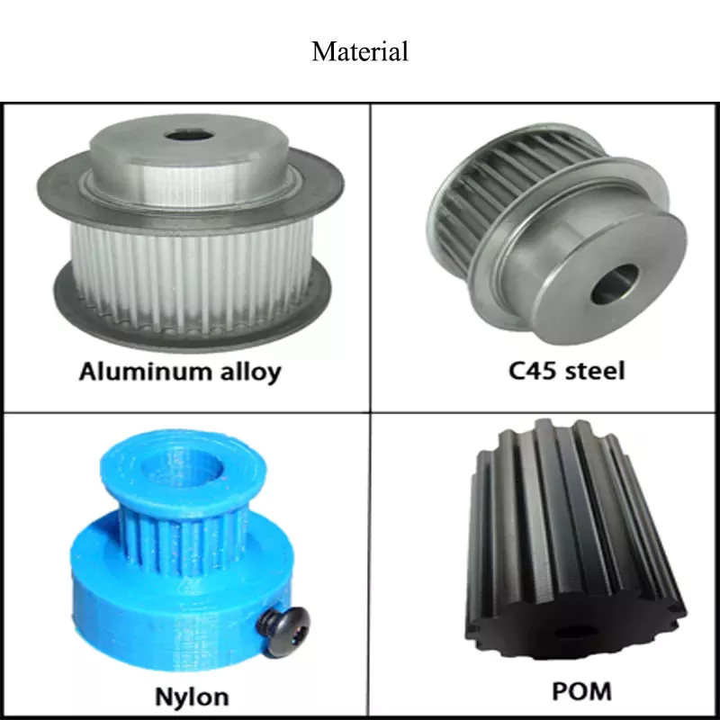
Mechanical advantage
Pulleys have been used to move heavy objects for centuries. When two rope sections are used, the weight of a 100kg mass can be moved with only 500 newtons of force. Adding an extra pulley increases the mechanical advantage. If the pulley has two wheels, the distance between the rope sections and the wheel grooves is only half the distance, but the mechanical advantage still applies. Adding another pulley increases the mechanical advantage, but can be risky.
Mechanical advantage is the ratio of force used versus force applied. The calculations are made under the assumption that the ropes and weights do not elongate or lose energy due to friction. If the weights are very light, the mechanical advantage is greater than that in the real world. To calculate the mechanical advantage, the weight of the load to be lifted must be the same as the weight of the person using the pulley.
A single moveable pulley has a mechanical advantage of two. The weight passes around the pulley, and one end of the rope is attached to a fixed point. The pulling force is then applied to the other end of the rope. The distance the weight travels doubles, or halved, depending on the direction of the pulley. Adding a second pulley reduces the distance and the effort required to lift it.
There are several ways to calculate the mechanical advantage of a pulley system. Some methods are specific to certain types of systems, while others work for all systems. The T-Method is a good choice in many applications, as it calculates the units of tension for each rope segment. Once you have determined the input force, you need to determine the maximum force that will be applied to each component. A compound pulley, for example, will require 4 units of tension for each rope segment.
In simple terms, the effort is the amount of force needed to lift the load. This force is measured in newtons (N). A mechanical advantage is often presented without units. If the student does not have this unit, you may need to convert the units to newtons, since one kilogram is equal to 10 newtons. If you can’t figure out the units of effort, you can use the KWL chart provided by the teacher.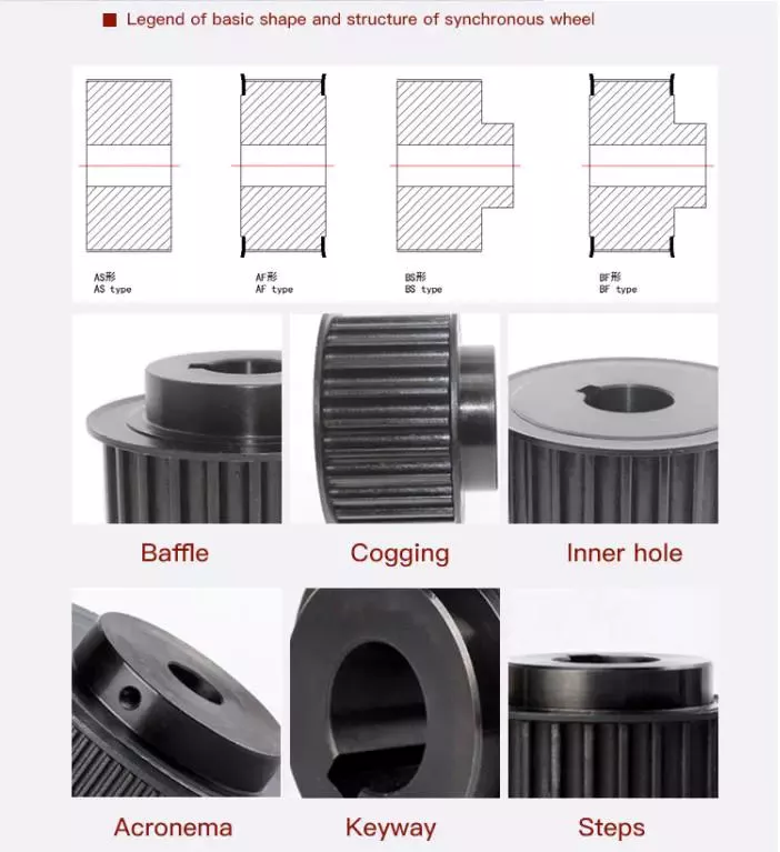
Safety precautions
There are a few safety precautions you should take when using a pulley. First, always check the SWL (safe working load) before attaching anything to the pulley. This indicates the maximum weight and angle the pulley can safely handle. Second, make sure that your work area is free from people and debris. Third, wear a hard hat to protect your head from blows and falling objects.
Another important consideration is anchoring. Although the pulley reduces the weight of an object, it is not enough to eliminate the weight. This is especially true if you are hoisting a heavy object, such as a motorcycle or lawnmower. It is important to ensure that the anchoring point can support the entire weight of the load. It is also important to follow proper anchoring procedures when using a pulley to lift a motorcycle or lawnmower.
In addition to the safety latch, you should use a tag line to control the suspended load. Remember that a chain pulley block is necessary for vertical lifting. You should also wear personal protective equipment (PPE) while using a pulley to avoid injuries. If your workplace does not have an PPE policy, you should consider implementing a similar policy. These safety guidelines are a good start.
If you are using a pulley to lift heavy objects, make sure to wear gloves. Those who are not familiar with rope-pulling will have an easier time demonstrating how it works. If you are using a rope-pulley system in a classroom, be sure to follow lab safety guidelines. Wear cloth gloves, clear the area, and do not jerk the rope. In addition, never allow yourself to be pulled into the rope by an unfamiliar person.
Another important safety precaution when using a pulley is to ensure that the anchor point for your system is adequate to support the weight of the object being lifted. Check with the manufacturer of the pulley to find out what its weight limit is, as some types of pulleys are designed to lift much heavier weights than others. It is important to follow all manufacturer’s instructions when using a pulley.


editor by czh 2023-01-29